Authorized Distributor
Contact us today!
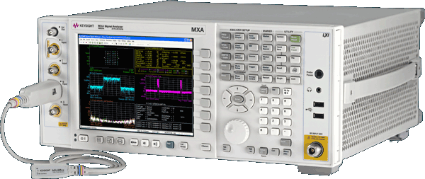
N9020A MXA Signal Analyzer
Accelerate the Development of Wireless Devices with the Speed, Performance & Applications to Adapt to Evolving Test Requirements
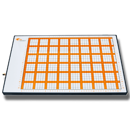
EM Scanner - YIC Technologies
High speed 8GHz Real-time EMC and EMI diagnostic tool on your lab-bench
Authorized Distributor
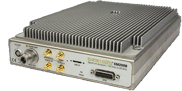
SM200B Spectrum Analyzer
The High Performance SM200B From Signal Hound: High Performance Speed, Accuracy, Security, and Agility Meet Very Low Cost
Categories
- Analyzers->
- Generators->
- Meters->
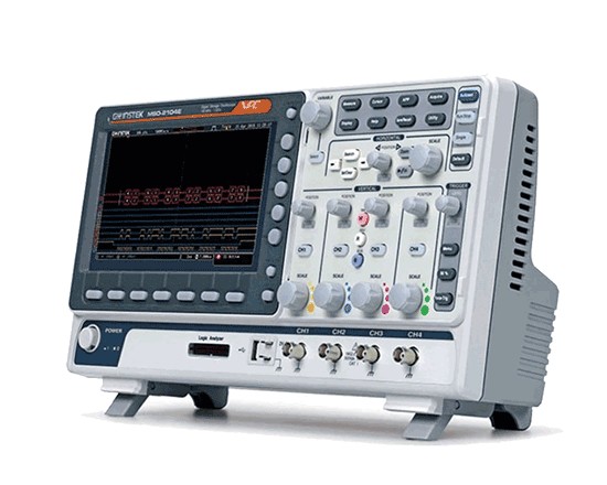
- Oscilloscopes->
- Power Testing->
- Other->
- EMC EMI->
- ¬ Absorbing Clamps
- ¬ Analyzer Bundles Near and Far
- ¬ Anechoic Chamber Alternatives
- ¬ Antennas
- ¬ Antenna Kits
- ¬ Antenna Masts
- ¬ CDN Coupling Decoupling Networks
- ¬ Conducted Immunity System CIS
- ¬ Comb Generators
- ¬ Current Probes
- ¬ Directional Couplers (DCD, DCU)
- ¬ EMField Generator
- ¬ EMI Test Receivers
- ¬ Enclosures
- ¬ Line Impedance Stblzr
- ¬ LISN
- ¬ Transient Limiters for LISN
- ¬ Near Field Probes
- ¬ Power Amplifiers
- ¬ Preamplifiers
- ¬ Precompliance EMI Test Systems
- ¬ Scanners
- ¬ Telecom (Part68 CS03)
- ¬ Turntables
Manufacturers
Testimonials
-
★★★★★
"Fantastic deal. The oscilloscope is in very good condition. Packed for shipment to survive anything"Jeff
-
★★★★★
"Premium equipment. Excellent communication. Fast. Best value!"Avi
-
★★★★★
"Practically in new condition"Darcy
-
★★★★★
"There was a small issue; The people at BRL Test were 100% responsive and issue resolved. Thanks!"Mike
-
★★★★★
"Best packing ever! I would let you ship one of my children!"Todd
-
★★★★★
"Unit received in great shape. Passed Agilent calibration. Good job!!"Lee
-
★★★★★
"In every aspect these guys are great!"Sarah
Join our Newsletter

BRL TEST INC
Your IP Address is: 216.73.216.127